Pass-through switch: characteristics, types and diagram of the device
Feedthrough switches (switches) wereThey are designed for convenient lighting control in long corridors, on stairs, in walk-through rooms and in other places. They are installed between floors, when descending to the basement, near the doors of the premises, which have several entrances. Being in his house, it is convenient to switch the light in the garage, utility rooms. Or to operate lanterns on a porch and a personal plot. The pass-through switch makes it possible to control lighting from different places, relieving people of the inconvenience. This also saves electricity.

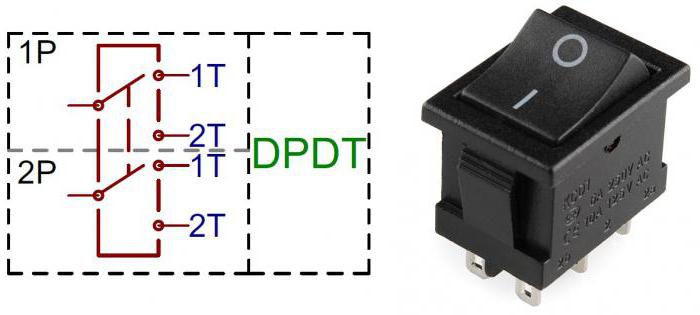
A conventional switch contains a key for twoposition and a pair of contacts. The wires are connected to them. In contrast, the built-in switch of the pass-through switch consists of three contacts: one common and two change-over switches. Each of them is also connected by wire. To control lighting from several locations, for example two, a switching device is required for 4 contacts. In addition, there must be carts to each one by one wire. So, you can control not only lighting, but also any other electrical appliances, although the installation of the circuit is complicated.

How does the one-button switch work?
The principle of action is that the perekidnymthe contact opens one circuit, and the other closes. The wiring switch is always connected on its reverse side. One of the contacts is common (1), and the other two are flip-flops (2, 3). From two such devices located in different places, it is possible to assemble the simplest and most common control scheme of the luminaire from two different points.

Matching by the numbers of terminals 2 and 3switches PV1 and PV2 are connected with each other by wiring. Input part 1 from PV1 is connected to the phase, and PV2 - to the luminaire. The other end of the lamp is connected to the zero supply wire. How the circuit-breaker circuit works, is checked by switching it on. To begin with, the voltage is applied. At the same time, the lamp lights up sequentially or goes out with independent switching of any of the switches. If the circuit of one of them is broken, the circuit stops working. But at the same time another line is being prepared for inclusion.
How to connect the simplest pass-through switch?
Before installation, draw a diagram of all connections.
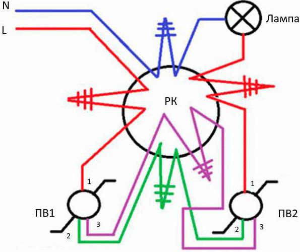
First the junction box is installed(RC). In it, all wires will be assembled and connected. Power is supplied from the control panel. For this, a 3 x 1.5 mm three-core cable is laid. It is most common for all connection schemes. Here, two cores are feeding, and the third is for grounding electrical appliances. In addition, 2 podzrownets are installed in which the switches will be placed. From each glass and from the lamp are laid three-core cables to the RC.
After all wires and cables are on thetheir places, connections are made. First, connect the phase L wire between the output of the machine and the input of PV1 (No. 1). Then the respective output contacts (2-2, 3-3) of the switches are connected to each other. Next, they are installed in the sub-socket. Two terminals of the lamp holder are connected to the input of PV2 (No. 1) and to the blue core of the neutral from the control panel. If the machine is bipolar, it is fed from its output terminal, if a single pole is from the zero bus. The end of the earth conductor is isolated. Or it is connected to the luminaire case, if it is metal.
When all connections are completed, the cartridgeis turned on lamp. Then the circuit of the bypass switch is checked by switching on the automaton in the shield. The lamp can catch fire immediately. Or after the inclusion of PV1 or PV2. You can cancel it by pressing any of the switches. Important! The switches do not have fixed "on" and "off" positions.
Cross Switch
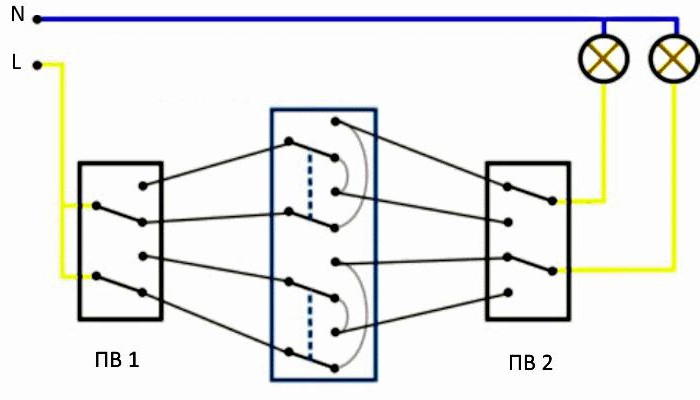
Connection of pass-through switches in threeplaces requires an additional installation of a device with cross-switching of contacts. It represents 2 one-button devices with internal jumpers assembled in one housing.

The cross switch (PCB) is installedbetween two ordinary. It applies only to them. Its distinctive feature is the presence of four terminals (2 inputs and 2 outputs). To manage from four points, you need to add another such device to the circuit. Connect the circuit breaker to the changeover contacts of the feedthrough switches in such a way that the working circuit of the luminaire is created.
Complex contact groups require a large number ofnumber of wires and connections. It is preferable to collect several simple schemes. They work reliably and are easy to use. Note! All basic connections are made in junction boxes. No twisting on the lead wires can not be done.
Which model to choose?
Which one to apply a pass-through switch, beforedepends on the type of wiring. Overhead models are chosen for open. Under the concealed will require podrozetniki. It is necessary to choose suitable dimensions so that they can be joined together. It is important to install a conventional and cross-over switches with the same appearance. Devices are swivel, keyboard, lever, touch. Contacts are selected for the appropriate load. Switching should be done easily. In this case, the devices must be securely fastened.
Installation of a three-point switching system
To do this, perform the following actions:
- Draw a connection diagram.
- Mark and continue grooves and grooves for wiring and boxes.
- Install the distribution parts. They are selected in large sizes so that 12 connections can be made inside.
- Install the podzroetniki.
- Route the cable from the shield to the connection points.
- Connect the wires to the switches and terminals in the boxes. Mark the wires. Scheme to collect sequentially, with the verification of the correctness of the connections.
- Set the switches to their places.
Connection of two-key pass-through switches
The device consists of 2 single-keyindependent switch. They are assembled in one body. Work on the same principle of throwing contacts. But the number of inputs is 2, and the number of outputs is 4. The difference lies in the fact that 2 switches are located at different points. Their keys work on different fixtures.
Installation of two-key switches for control from two places
The sequence of actions should be as follows:
- A circuit is made without which it is difficult to make connections.
- Junction boxes and sub-boxes are installed.
- Two groups of lighting are mounted.
- Three-core cables are laid at the rate of connection to 6 contacts of each switch and to the luminaires.
- According to the designed scheme, the cable cores are connected in the junction box, lamp holders and switches.

The two-key pass-through switch can be replaced by a circuit of four one-button ones. But it will be irrational. Since more junction boxes are required and the cable consumption is increased.
Control of two lighting systems from three locations
Two-key toggle switch iscross. It is installed in the kit. That is, it also includes two two-key limit switches, if you want to control lighting from three points. It will have 4 inputs and 4 outputs.
Installation is as follows:
- For the installation of a standard box with a diameter of 60 mm is not enough. Therefore, its size should be larger. Or need to consistently install 2-3 pcs. conventional.
- 12 connections are available for connectionwires. To do this, you will need to install 4 three-core cables. Here it is necessary to correctly mark the cores. To the two limit switches, 6 contacts are suitable, and to the cross - 8.
- A phase is connected to PV1. After you need to make the necessary connections. On the back side of the device is a schematic diagram of the two-key pass-through switch. It should be correctly combined with external connections.
- PV2 is connected from luminaires.
- Four outputs of PV1 are connected to the inputs of the cross switch, and then its outputs are connected to 4 inputs of PV2.
Conclusion
The switch is convenient. There is no need for unnecessary walking on the stairs and long corridors to turn on or turn off the light bulb. Sometimes it is just necessary. In addition, energy is saved by fast switching. It is important to select the right devices and correctly mount electrical connections.
</ p>>